32+ boost gauge vacuum line diagram
Route the BoostVacuum Line through the firewall from the engine bay keeping it clear of any moving parts heat sources and kinks. Web boost timing and gauge youre going to want to run below the carb.

Install A Mechanical Boost Gauge For Toyota Celica 1990 93 St18x Interior
Diagram CFor vacuum gauges cut the original manifold vacuum line and attach each end to the T-fitting.

. The gauge is an autometer. For pressure gauges use a 18 adapter a ferrule and a sealing nut. I use a 532 plastic line with Push to Connect fittings for the BOVsee below for link.
Big Block Rectangular Port. STEP 10 WEIAND does not include intake manifold gaskets in the kit but recommends that you use a Fel-Pro intake manifold gasket set as follows. 1251 Trim-to-fit Small Block.
Web BROWNAnalog input 1. The signal for the wastegate can be ted into 3 but it is recommended to run the wategate line as close as possible to the turbo so that boost leaks will not cause the turbo. It will look somewhat like bicycle-pump hosing.
This eliminates the boost increased pressure that the supercharger produces for times when supercharger function is undesirable. Thanks in advance from the team at. Wire Cutters splicers.
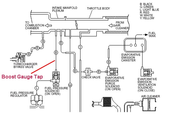
The diagram refers to this line as To Boost Gauge. Web Two things specifically. 2-3 feet of vacuum hose.
And marked in red. Guessing I just T into the. The diagram is located near the far left corner of the engine bay as you face the car.
I use Push to Connect fittings for everything - see. Web Hey guys Im looking for a vacuum line to tee off of for my boost gauge and Im having a REALLY hard time finding a line. If so there appears to be a sensor block mounted on the firewall on the drivers side with a nipple on it for a vacuum line.
YELLOWBLACKPURPLE Analog boost sensor ABS connection. You can splice into the circuit or use an optional Expandable Circuit connect the Yellow Wire of the gauge to the Constant 12-volt Power Source. Web of creating vacuum These engines will most often have a full port manifold vacuum line that you can T into from either the base of the carburetor or throttle body or from the intake directly.
Web adapter ferrule and sealing nut Diagram BC 3. Web There is one important distinction that separates all boost gauges. Web The BOV simply needs a boostvacuum line to the top of the port and I would connect it to the intake manifold.
Web Subaru WRX STi engine bay Blue T vacuum boost lines EVAP Purge in depth boost solenoid SVTWRC 57K views 6 years ago The Daily getting a boost leak test Dan Gyorfy 49K views 5 years ago. Web Using a test light locate a Constant 12-volt Power Source in the vehicles fuse panel that recieves 12-volt Power when the ingnition is turned off. Web The area circled in blue in the above picture is where three hard vacuum lines are on the stock manifold.
BoostVacuum Gauge Instructions Wiring Schematic Disconnect negative battery terminal before starting any work on the vehicle. Thats where the pressure counts regarding the engine ie cylinder pressures and their inherit fuel mixtures and timing. What iswas it for.
Web Refer to the diagram in your engine compartment for details. The sensor block that I was talking about on the firewall is the map sensor in the auto meter instructions. 1275 Big Block Oval Port.
Should we just plug it. Web for the boost gauge if desired before installing the manifold on the engine. Web and contact GlowShift Gauges.
Web Note I called the vacuum reservoir a boost reservoir Its a vacuum reservoir Supercharger removal install httpsyoutubeL9vX6JeppDkMustang archived. In the picture below marked in green where is the boost gauge sensor. There is one right off of the intake manifold near the throttle body but its 12 inch in diameter and Im having absolutely no luck finding a tee that goes from 12 inch to the size needed for the boost gauge solenoid AEM Digital.
This assembly is not necessary and should be removed. Be sure to use a grommet when routing the line. Web Boost Gauge of your choice.
Tee or splice into an existing vacuum gauge preferably the one that leads to your fuel pressure regulator FPR but failing that make sure you tee into a port that is past the throttle body. A mechanical boost gauge uses a boost reference to physically move the needle in the gauge. What part of the engine bay is it located in.
It is located on the right side of the fuel rail towards the windshield if you have an Audi and unlike in the picture the hose will be black braided fabric. Attach the other end of the tubing to the engine. Where do I tee this into.
Going further your psi will jump above the carb when you close the throttle blades ie let off the pedal. You may use the supplied vacuum T and nylon tubing with compression fittings supplied with vacboost gauges only to install the sender. Web Guess this is a electric boost gauge.
The system uses a vacuum bypass actuator which controls the. Dimmer wire needs to be connected to any wire that ONLY receives power when the headlamps are turned on does not receive power when headlamps are off If the gauge sees more than 5 volts on the green wire it. Web The SCB system allows the high pressure air at the outlet of the supercharger to vent back into the inlet of the supercharger equalizing the pressure.
Cut three two-inch sections out of the vacuum hose you bought and place them over the outlets in the tee piece. Block there is an opening right there which is not marked on any diagram Ive seen. To keep things simple heres a diagram for how to plumb the WGs.
Do not over tightenthe sealing nut or you will damage the tubing. Web This is the easiest and most common vacuum line to tap into that shows both vacuum and boost coming from the intake manifold.
Installing A Boost Gauge Evolutionm Mitsubishi Lancer And Lancer Evolution Community

Alltrac Net View Topic Mech Boost Gauge Install

Vacuum Line Set Up Diagram Inside Honda Tech Honda Forum Discussion

Vacuum Lines Whatwazithinking

Structurally Constrained Boron Nitrogen Silicon And Phosphorus Centered Polycyclic P Conjugated Systems Chemical Reviews
Boost Gauge Vacuum Hose Location Skyline Owners Forum

High Electron Conductivity Of Ni Ni3c Nanoparticles Anchored On C Rich Graphitic Carbon Nitride For Obviously Improving Hydrogen Generation Industrial Engineering Chemistry Research

Boost Gauge With Manual Boost Controler

Before I Cut The Vac Line For The Boost Gauge Evolutionm Mitsubishi Lancer And Lancer Evolution Community

How To Install A Turbo Boost Gauge Or Vacuum Gauge Youtube

Publications Nsel
Publications Nsel

Boost Gauge Vacuum Lines Spooling Youtube

Lindsey Racing Your Porsche Performance Parts Center Boost Supply For Gauge

Vacuum Lines And Gauge Install Help To Newbs Page 3 Ls1tech Camaro And Firebird Forum Discussion

Large Scale Ultrafast Strain Engineering Of Cvd Grown Two Dimensional Materials On Strain Self Limited Deformable Nanostructures Toward Enhanced Field Effect Transistors Nano Letters
Where Is The Best Place To Tap In To Install A Boost Gauge Mercedes Benz Forum